So in my last post I showed how to get started in georeferencing with the first overlay. In that post I put the second layer in to show how it would join onto the first layer. The aim of this part is to show how to add additional overlays and how to deal with the overlap between one layer and the next.

Right now from the last post this is what I can see on my computer screen of the Whangarei rail yards and sidings. Whangarei has a main station yard and a separate port area with its own sidings. The port used to handle container traffic until it was all moved to Marsden Point (which is near the heads of the Whangarei Harbour, whereas Whangarei is at the top) around 20 years ago. There has been huge debate ever since over the lack of a rail link to that port, and the rail-friendly Clark Government started the process to build the spur line that would come off the North Auckland Line at Oakleigh, only 14 km south of Whangarei. But then there was an election and the anti-rail Key administration came into power and stopped all the rail work. It is now being resumed by the Ardern government and probably the construction will be approved to start in the next 12 months. Anyway those port sidings are still in place to some extent and some ships still come into the port so the maps of Whangarei will document that but we need seven overlays in the D series and two in the F series, a total of nine. I am also mapping Kamo which is to the north of Whangarei as the same series of aerial photos Survey 2788 has two runs that cover that part of the Whangarei urban area and the Northland 0.1 metre urban area aerials are also available for there.
But for now let’s have a look at overlaying D 5 onto D 3. As you can see I am not getting across much distance with each overlay. I can do a rough measurement from the grid because I know there are 4800 pixels wide and 7200 pixels high and each pixel measures 0.1 metres on a side, so with the two overlays so far covering roughly 2 high and 2 wide, so far we have covered an area 960 metres by 1440 metres, or 0.96 km by 1.44 km. It’s easy from that to understand how the disk space gets gobbled up because I have to be able to work at this high resolution to get the detail visible down on the ground that I need and that means a lot of layers. This particular project file covers Oakleigh, Portland, Whangarei, Kamo and possibly Hikurangi / Waro in one canvas which is not continuous but broken into separate areas for each station, and it’s currently on a 52800×108000 canvas with 69 layers and is taking up 10 GB on the disk. As I mentioned previously my rules are not to exceed 100 layers and 20 GB disk size although I do have a small number of projects that are around 30 GB but Gimp doesn’t seem to be able to handle much larger than this without crashing a lot. But when covering a long urban corridor and having to split it across multiple files, then an extra complexity is to deal with the overlaps between the edges of each file. Of which more later.
One of the reasons progress is slow is that even with skipping to every second image in the NZR survey, there is still up to 50% of each image overlapped and that is a lot as you can understand. It lends weight to the idea of taking all the images in the survey and just chopping the middle out of them. That is something I might try with Kamo because I could save a lot of disk space that way because the overlapped pixels are just wasted duplication that uses up storage.
So now in Gimp I’ve selected D 5, put it into unified transform, and started lining the top of it up with the bottom of D 3. Now, it pays to be smart about the order in which Gimp draws layers, because there is this overlap in the case of these overlays. The base aerial photos are all nicely broken up into tiles that don’t overlap, they all just nicely fit against each other in the grid, but we don’t have that convenience with the overlays. So if I have three layers in the layer list the highest up one will be drawn over the top of the ones lower down in the list. And that calls for some careful thinking when doing the unified transform, because what you see in the preview is the overlay that is selected for the transform, drawn over the top of all the other layers and contradicting the order in which it will actually be drawn when the transform is completed. Here’s a screenshot that illustrates that pretty neatly.

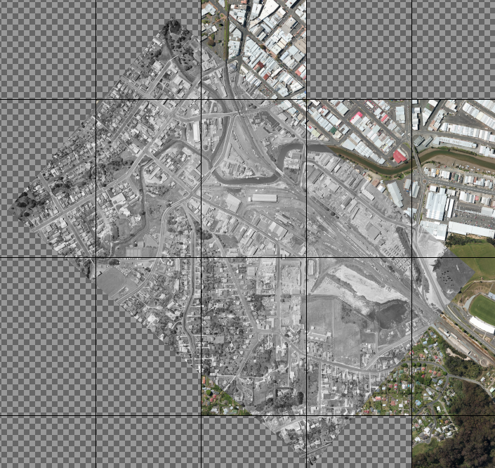
So what you can see happening in this screenshot is I’ve done the first stage of overlay transform. I’ve put the pivot right up the top of D 5 at a point that I am confident I can line up on that is also present in D 3, and then I’ve gone down to the bottom of D 5 and dragged a size handle to size the overlay to match the surrounding terrain pretty well. So we start by overlapping somewhere near the top of our current overlay, because that is the easiest until we get the overlay to the right size. Then once we have that sorted, we now have to “underlap” as I call it. We have to align the overlay at the bottom of D 3 because that part of D 3 will be drawn over the top of D 5 all the way to the bottom edge of D 3. You can see where the overlay transform’s frame is, the handles and the pivot at the top of the frame. But down near the bottom of this screenshot, what’s underneath changes to colour instead of black and white. That’s where the bottom edge of D 3 actually reaches to and that’s where it is most critical to actually line up D 5 because that is where the join between the two layers will actually be drawn.
When you come to do overlays on rail tracks, these old aerial images have marks that were specially placed on the ground by NZR staff. They would paint a sleeper completely white over its whole top and then add white paint on the centre sections of the sleepers on either side. The frog rails and guard rails on turnouts are usually also painted white, but this is more to highlight them as a safety hazard when crossing over the rails in the yard, as someone could get their shoe stuck in the gap. This is what the result looked like. The purpose of this was to make it possible to overlay the aerial photos into a mosaic that was printed out on a big piece of paper that was used by the engineering staff. I have seen these big printed plans which were over a metre by a metre when printed out and some of them are in storage in archives around the country.

It is a bit harder to get the join between two layers exactly right when it isn’t actually on one of the overlay edges, partly because you have to take the preview opacity up and down to check the fit, and because the overlay at 100% opacity will not show the join at all, it will look like the join is at the top of D 5 instead of at the bottom of D 3. Before Gimp was updated to 2.10.18 with the Readjust feature, it was a lot harder to do a proper alignment at these joins and one trick I used was to do the overlays starting from the bottom of the Gimp layer list instead of the top because the preview would be correct for the layer order, another trick was to reorder the layers in the layer list if the join ended up being rough. But especially since Readjust became available it is now much easier to do these joins really smoothly and that has made a big difference to this task.
So now I am going to move the pivot down to the bottom of D3 and line things up down there. At this stage I still have the transform frame at the full size of the overlay and haven’t used Readjust, which moves the frame and changes its size. By bringing the preview opacity up and down and finding the exact point of overlap, I can get a very smooth join. Here the shortcut keys I have set up to step opacity up and down 10% per step are very useful to preview what the join will look like. Basically you are comparing the overlay at 100% to the overlay at 0% and looking at how smoothly it overlaps close to the join. You can get a pretty good feel for how that join will look and in the case of a rail yard or some other situation where the join is wider than a track or two, you want to be checking all the way across. Bring the pivot down to that join, put it on some key feature like a main line, and if necessary use the Readjust to change the size of the overlay at the join so you can get it looking really smooth. Just remember Readjust moves the pivot to the centre of the new transform frame, and that you can only ever reposition the overlay by dragging inside the transform frame regardless of its size.
Once you have that pivot in place and have the join looking good you need to check at the edges of the overlay again for the underlying base imagery you are lining up on, if necessary using Readjust to make a really good smooth alignment, again being aware with Gimp 2.10.18 you need to move the pivot back to the join when you press the Readjust button, then finalise by checking the join is still correct, and then we are ready to transform. In this case the most important alignment for the bottom of the overlay is the main rail line heading south, and for the sides, it is the surrounding streets and houses, because with no clear features near the bottom to ensure we have the bottom of the overlay in the right place, we have to use features out to the sides to help check our alignment. Here’s the result as we have it now, with a really smooth join that I am not going to zoom in but I got it really neat again across the rail yard, but with varying results further out, as we’d expect.

And so I will carry on with the rest of the overlays to get all the way down, all nine of them.
There is one more thing to mention and that is when you are doing a continous corridor, like in an urban area. In reality, NZR had corridor surveys of various types done, with the major main line corridors completely covered, but it’s impractical for me to do that myself and use all those aerial photos. So typically in rural areas I am just doing a few stations by themselves, but in the major urban areas, such as the five main centres, continuous corridor is what I do. Now it’s inevitable that I will hit the layer or file size limits that I work to and such a segment of corridor will end up being split over more than one file. For example earlier on I did a continuous corridor from Newmarket to Waitakere in Auckland which is a total of 36 km that ended up going across three files in total. When you get to the edge of the current file what you do is copy the overlay that is at the edge and the underlying base layers to a new file. There are a few ways of doing this such as creating a layer group, putting the overlay and base layers relevant into it and then dragging it to a new canvas and then saving that to a new file. Another is to crop the original image down to the base layers that cover the area occupied by the edge overlay and then save to a copy of the original file. The reason for base layers being saved with the overlay is in the new file you can drag all the layers together (including the overlay) by using the layer linking in Gimp’s layer list, into the grid in the new file so that the base layers are lined up properly in that grid, and then add the rest of the base layers and overlays as required to the file. This ensures you don’t have to realign the overlay and also that the overlay is still exactly in the same position as it was in the original file, so that new overlays you add to the new file can be aligned to it and therefore the extracted tiles will line up perfectly in the GIS.
Part 6 is going to look at how to extract tiles for a GIS from the Gimp mosaic projects I have been creating, because that is the ultimate aim of this process.